H2S & H2O Monitoring Made Simple
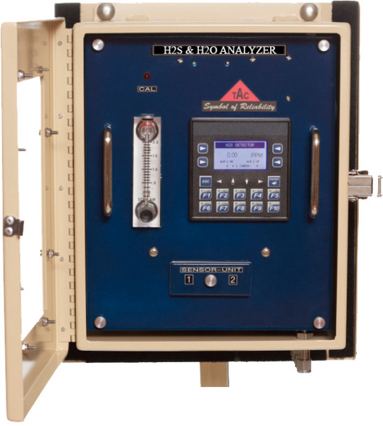
Choose Texas Analytical Controls for reliable, economical H2S & H2O monitoring. With two H2S sensors and one H2O sensor, the TAC analyzer is your first choice for reliable H2S & H2O monitoring in the field.
If the output of one sensor fails, you can easily disable it. The analyzer will continue to operate reliably, assuring you of consistent H2S monitoring over time.
Easy to Operate and Maintain
The TAC analyzer outshines the competition when it comes to ease of operation and maintenance.
The H2S Sensors typically last a full year and can be changed in just a few minutes. The H2O sensor typically lasts 2 years and is also very easy to change.
The H2S Calibration is simple and can be done in less than six minutes. Calibration can be set up to occur automatically, reducing the time required in the field, or can be performed manually.
The H2O portion is factory calibrated with no field calibration required.
Full Technical Support
You will find the analyzers are easy to maintain. Technical support is available via phone or in person by one of our service technicians.

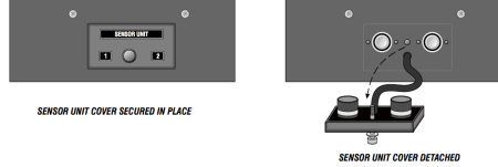
We have updated our analyzers so that replacing H2S sensors are done by removing just one thumbscrew. Click “VIDEOS” tab and watch “How to Replace H2S Sensors” |
 |
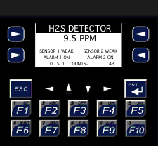
The analyzer will display “Sensor Weak” when the H2S sensors are 75% used. This new feature provides the operator a warning to change the sensors. (Sensor Weak Indication is supported only with H2S) |
 |
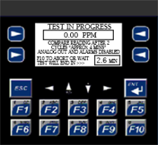
A bump test can be performed to verify readings without removing the sample line. This also saves the operator from completing a full calibration that takes 10 minutes. |
 |
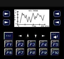
Displays Historical Trend of H2S & H2O Readings within the previous hour |
 |
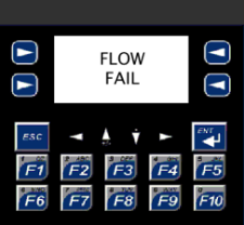
The display will read “Flow Fail.” If the regulators and the flow meter(s) are not working properly and the sample line is obstructed. |
 |
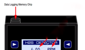
The SD memory card is used to store Historical Calibration and Alarm Data. Each analyzer has the ability to be given a Name or ID. The selected ID name will also be displayed when downloading data from SD card to a spreadsheet. |
 |
| Range | Customer to specify a range and can be field programmable to alarm at any desired set point. Typical ranges:
|
| Detection Method |
|
| Calibration | An LED indicator on the front panel illuminates when the analyzer is in calibration mode. Display shows “Cal Complete” after a successful calibration Calibration can be performed Automatically or Manually |
| Communications Output | 4-20 mA (Self Powered) Modbus (See Customization Tab for other options) |
| Sample Input Pressure | Inlet 10+/-2 PSIG |
| Response Time | < 60 Seconds |
| Instrument Accuracy | +/-5% of the Full Scale |
| Instrument Repeatability | +/- 2% |
| Current Draw | < 1 A |
| Operating Temperature | -20°C to 50°C; -40°F to 122°F |
| Range | H2S
H2O
(Customer specifies desired range in PPM or %) |
| Communications Output |
|
| Power Input |
|
| Alarm Relays | Two Independent SPDT Relays for Low and High Alarm Alarm Setpoints, Latching, and Non Latching are PLC Programmable Relay Ratings:
|
| Alarm Delay | An Alarm Delay is PLC Programmable The delay can be set for 0-90 minutes |
| Shut-In Valve | Pneumatic solenoid valve or relays to control your shut-in valve |
| Enclosure |
|